Pyro Propeller Clock POV Project
Written on 10:21 by XXX
Propeller clocks are nothing new to anyone who has been into electronics for a while. They use an idea called POV, Persistence Of Vision, which means that if something appears in the same spot consistently, at least 50-60 times per second, our brains think that it's permanently there when it really is not. TV's and Monitors use this method of display, so it's not as uncommon as you might think.
After having seen so many propeller clock POVvideos on Youtube, but no real description of how they work or how to build your own, I set out to make one and document how it was built. The Pyro Propeller Clock POV design criteria was short and sweet: be as simple as possible in order to encourage others to make their own, DIY style.

Purpose & Overview of this project
The goal of this project is to make a single color propeller clock that uses POV for a cool optical illusion. The propeller should be able to display at every angle 0° - 360° in 1° increments. An IR transmitter receiver pair should be used as a 'home' point for the propeller clock.
To keep things simple, all parts will be off-the-shelf and modified for our needs. The propeller clock will use two power supplies, one on-board the clock and another to drive the clock motor. The basic operation of the propeller clock will be: starting from 'home', every 1° display a specific LED output that correlates to that location until home is reached again (at 360°).
DETAILED PARTS LIST
Parts List Details
This project has a lot of parts and each one serves a vital purpose. While most of these parts have already been explained in the prerequiste tutorials tutorial one andtutorial two, I'll explain below what the most important parts are for this project and what their specific function is.
PIC 18F252

This is a small microcontroller made by Microchip Technology. Their microcontrollers are widely used in industry and are high quality. This controller is responsible for catching the 'home' point signal and for outputing LED signals at the proper times in order to create the POV optical illusion that propeller clocks are known for.
74LS373 - Latches

These are low power schottkey data latches. They will control which leds are currently on, by providing a ground (output +0v) for current to flow through the LEDs. If the ouput state of the 74LS373 latches are high +5v, ground is cut off and therefore the LEDs are turned off.
40 MHz Crystal

The PIC can run up to 40 MHz, so feel free to use faster or slower crystal speeds. 40 MHz was semi-randomly chosen from what parts I had laying around. If you use a different clock speed, you will have to change the software as a differeny crystal speed will change the timing.
Desktop Fan (3800 RPM)

Using a desktop fan as the module to spin the propeller clock is a good design choice because speed and power control circuitry is already built into the fan. We only have to turn it on and it will do the rest of the hard work. You should have a fan that spins at least 3600 RPM in order to create the proper POV effect.
Infrared Emitter Diode and Phototransistor

This pair will be used to define a 'home' point. The IR emitter diode will shine a light into the phototransistor causing an interrupt to be triggered in the microcontroller. This interrupt will shout loud and clear that 'home' has been reached and software should be reset to begin displaying the POV image from the beginning.
Nuts/Bolts, Cake Platter and Misc.

All of the Nuts and Bolts used in this project are SAE size 6-32. I just found something that fit for the Fan. The Cake Platter was used in the previous Tupperware Turret project and will be used again as a platform base for this project. Other small parts were used like the 9v battery and some switches. The hardware section pictures should unravel any mystery of what parts go where.
Schematic Overview
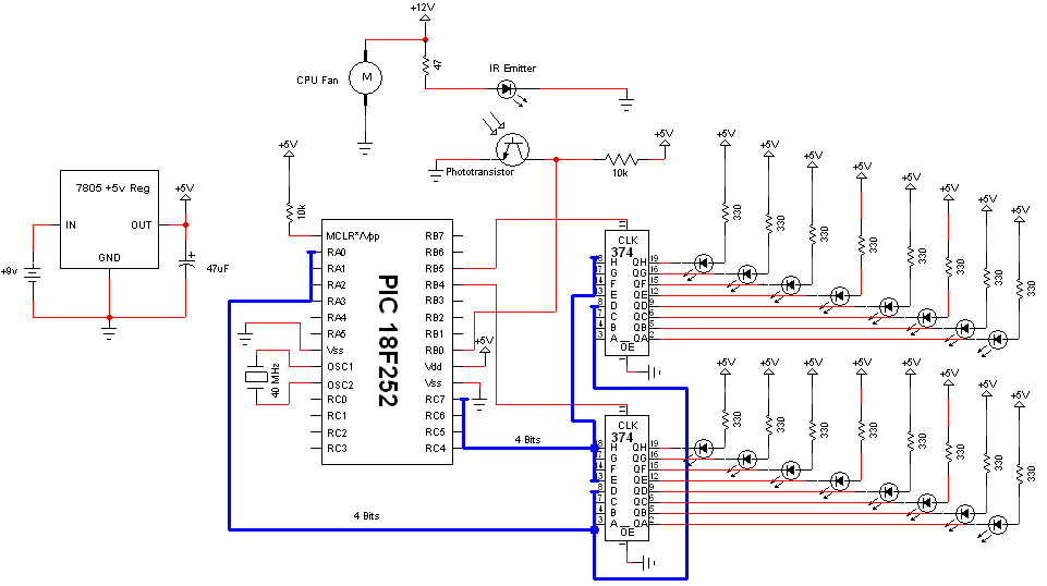
The Pyro Propeller Clock POV schematic is actually not very difficult. There are three main parts: the power supply which uses a 7805, the LED output control which uses the PIC18F252 and 74LS373 and the 'home' trigger circuit which uses an IR emitter and Phototransistor.

Schematic Specifics
Power Circuit
This standard +5v power regulation circuit makes use of the LM7805 3-pin T220 device. A DC filtering capacitor is attached to its output to prevent high frequency spikes from the power supply.
LED Output Control
The PIC 18F252 uses an 8-bit data bus system with 2 control lines to tell which 74LS373 latch to output data on the bus to turn on/off LEDs. With this design, we can only send data to one 74LS373 at a time, which just means LED output updates will be nearly simultaneous instead of 100% simultaneous.
The Home Trigger Circuit
In order to know when the system should restart displaying the current image on the propeller clock, we need a known reference point called 'home'. An IR emitter diode shines bright into a phototransistor. This turns the transistor 'On' connecting the +5v collector pin to the +0v Emitter pin. The PIC 18F252 will see this 'falling edge' transition and know right away it's back at the home location, 360°.
Data Latch Theory
The 74LS373 data latch is used in my design as an LED driver. The output from the latches tells the LEDs to turn on or off. Since there are 13 specific LEDs that need to be individually controlled, each LED is connected to a specific data pin on one of the latches. This pin now controls whether an LED is turned on or off.

How We Will Use The Data Latch
Since there are 360 specific spots that we want to output to the LEDs, we must create a function that can set the leds to a certain value and then clear them. The picture above shows the flow of data from the PIC telling the latches which LEDs to turn on at every specific 1° interval. If done correctly witht he right timing, this should create the correct pov 'optical illusion' and show up as the image we want to see.
Propeller Clock Timing Theory
In order to output at the same location consistently as is required to create the POV 'optical illusion' we must have perfect timing. Luckily, the PIC 18F252 has a digital timer that will let us do just that!
Calculating Each Timing Step

Since we know the FAN's RPM, we can use some math to find out the delay between 1° intervals for LED outputs as the fan turns the propeller clock around the circle. The calculations seen above use our known RPM value to find out how long it takes to travel from 1° to 2°. This value: 43.85uS is how often the timer should be set to interrupt and update the output leds. If there are led outputs at every 43.85uS then there should be 360 specific locations where the LEDs can be seen when the fan is turning full speed.
IR Home Sensor Theory
To make this system more fault tolerant, a 'home' location is built to tell the system when it has reached 0° and to restart outputting the image. The circuitry used to build this home sensor are the IR emitter diode and Phototransistor.
<iframe width="640" height="360" src="http://www.youtube.com/embed/odIeL_zqwFY?feature=player_embedded" frameborder="0" allowfullscreen></iframe>
The video above illustrates how you can use a simple circuit (shown below) to detect if an IR Emitter Diode is present or not. When the IR emitter led is turned on, the phototransistors detects the IR light and switches the red LED (in the video) off. This simple idea will be used in the propeller clock to let us know when the propeller has passed over the 'home' location.
Propeller Clock IR Home

The picture seen above shows you where the 'home' location actually is on the pyro propeller clock pov. Whenever the propeller passes over the IR emitter, the phototransistor is turned on, connecting the 'collector' +5v pin to the 'emitter' ground. The PIC sees this 'falling' edge transition and knows that home was just reached.
Mechanical Hardware Design
Now that we want to start building the POV, the first thing we need to do is gather the parts, decide on a solid base to use and get the mechanical parts all drilled and screwed together.
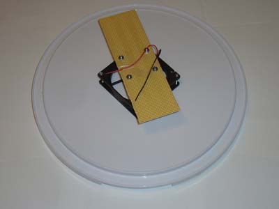
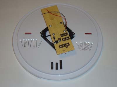
Building The Platform
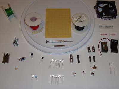
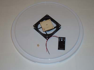
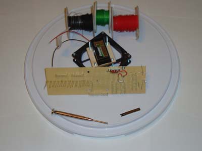
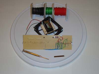
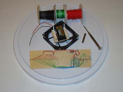
So, first off gather all of the parts together. The picture below shows you all the parts used to build the POV. The only part not shown is the +12v power supply for the fan and the IR led.


·Drill 4 holes in the base for the nuts.


·Cut a small piece of wood to glue/e-poxy ontop of the CPU fan.


Electrical Hardware Design
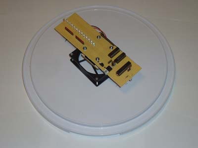
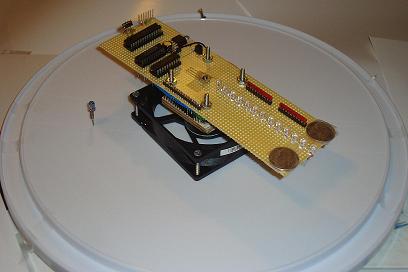
Strictly speaking, you just need to follow the schematic for this portion of the build process. Part placement can make the system vibrate a lot so either [a] try to balance the weight on both sides of the proto-board (you'll see later I added two coins) or [b] place the parts as close to the middle of the protoboard as possible.
Building The Circuit
Just like before, get all of the electrical parts together and let's get started soldering and wire-wrapping. As a side note: I had only seen PCB POV designs across the web and so for my design I thought I would prove to the world that an old-school wire-wrapped POV would work just as well.


The job of this high priority interrupt is to reset the timer0 so that it starts outputting to the LEDs from the very beginning. This is how the POV effect is created, by displaying the same pattern over and over many times per second. The led_count variable seen above is used as a timer interrupt counter to know which set of LED information to output. In the INT0 interrupt service routine it also gets reset.
Low Priority Timer0 Interrupt
The timer0 interrupt service routine decrements the led_count value and then uses it to dynamically know which leds to turn on and off. A big set of if/else statements were used for different locations and clock numbers/text that show up on the display.
What To Do Now
If you read through this project write-up, then I'm sure that you have seen other propeller clock POV's in the wild that are much more complicated. Those should give you ideas for other routes to explore for what else you can do to improve the project; most notably is using RGB leds so that the output can be any color that you want. Other designs have used wireless power transfer to keep the design down to 1 core power supply. These other paths are all good places to explore to build an even better propeller clock POV.
Conclusion
As it is, this pyro propeller clock POV turned out exactly as I had hoped. It is just simple enough, that I feel people can duplicate it with much less perspiration than it took me to build it, yet it still achieves the desired POV effect that looks so cool. However, the simplistic design has its trade-offs; especially in terms of reliability. The system created here could only run for a few hours before the 9v battery died, making this more of a novelty project. But if you are trying to build your own propeller clock POV for fun, then novelty is what it is all about!
If you have any further questions, I implore you...don't be shy, ask a question there. I check them out regularly and love getting comments & questions.
After having seen so many propeller clock POVvideos on Youtube, but no real description of how they work or how to build your own, I set out to make one and document how it was built. The Pyro Propeller Clock POV design criteria was short and sweet: be as simple as possible in order to encourage others to make their own, DIY style.
Purpose & Overview of this project
The goal of this project is to make a single color propeller clock that uses POV for a cool optical illusion. The propeller should be able to display at every angle 0° - 360° in 1° increments. An IR transmitter receiver pair should be used as a 'home' point for the propeller clock.
To keep things simple, all parts will be off-the-shelf and modified for our needs. The propeller clock will use two power supplies, one on-board the clock and another to drive the clock motor. The basic operation of the propeller clock will be: starting from 'home', every 1° display a specific LED output that correlates to that location until home is reached again (at 360°).
DETAILED PARTS LIST
Parts List Details
This project has a lot of parts and each one serves a vital purpose. While most of these parts have already been explained in the prerequiste tutorials tutorial one andtutorial two, I'll explain below what the most important parts are for this project and what their specific function is.
PIC 18F252
This is a small microcontroller made by Microchip Technology. Their microcontrollers are widely used in industry and are high quality. This controller is responsible for catching the 'home' point signal and for outputing LED signals at the proper times in order to create the POV optical illusion that propeller clocks are known for.
74LS373 - Latches
These are low power schottkey data latches. They will control which leds are currently on, by providing a ground (output +0v) for current to flow through the LEDs. If the ouput state of the 74LS373 latches are high +5v, ground is cut off and therefore the LEDs are turned off.
40 MHz Crystal
The PIC can run up to 40 MHz, so feel free to use faster or slower crystal speeds. 40 MHz was semi-randomly chosen from what parts I had laying around. If you use a different clock speed, you will have to change the software as a differeny crystal speed will change the timing.
Desktop Fan (3800 RPM)
Using a desktop fan as the module to spin the propeller clock is a good design choice because speed and power control circuitry is already built into the fan. We only have to turn it on and it will do the rest of the hard work. You should have a fan that spins at least 3600 RPM in order to create the proper POV effect.
Infrared Emitter Diode and Phototransistor
This pair will be used to define a 'home' point. The IR emitter diode will shine a light into the phototransistor causing an interrupt to be triggered in the microcontroller. This interrupt will shout loud and clear that 'home' has been reached and software should be reset to begin displaying the POV image from the beginning.
Nuts/Bolts, Cake Platter and Misc.
All of the Nuts and Bolts used in this project are SAE size 6-32. I just found something that fit for the Fan. The Cake Platter was used in the previous Tupperware Turret project and will be used again as a platform base for this project. Other small parts were used like the 9v battery and some switches. The hardware section pictures should unravel any mystery of what parts go where.
Schematic Overview
The Pyro Propeller Clock POV schematic is actually not very difficult. There are three main parts: the power supply which uses a 7805, the LED output control which uses the PIC18F252 and 74LS373 and the 'home' trigger circuit which uses an IR emitter and Phototransistor.
Schematic Specifics
Power Circuit
This standard +5v power regulation circuit makes use of the LM7805 3-pin T220 device. A DC filtering capacitor is attached to its output to prevent high frequency spikes from the power supply.
LED Output Control
The PIC 18F252 uses an 8-bit data bus system with 2 control lines to tell which 74LS373 latch to output data on the bus to turn on/off LEDs. With this design, we can only send data to one 74LS373 at a time, which just means LED output updates will be nearly simultaneous instead of 100% simultaneous.
The Home Trigger Circuit
In order to know when the system should restart displaying the current image on the propeller clock, we need a known reference point called 'home'. An IR emitter diode shines bright into a phototransistor. This turns the transistor 'On' connecting the +5v collector pin to the +0v Emitter pin. The PIC 18F252 will see this 'falling edge' transition and know right away it's back at the home location, 360°.
Data Latch Theory
The 74LS373 data latch is used in my design as an LED driver. The output from the latches tells the LEDs to turn on or off. Since there are 13 specific LEDs that need to be individually controlled, each LED is connected to a specific data pin on one of the latches. This pin now controls whether an LED is turned on or off.
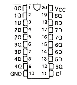
Each data latch has two control pins: Latch Enable and Output Control. Below I will briefly describe how the control functionality works and how it will be used in the propeller clock.
Output Control (OC) enables or disables the output pins. If they are enabled, data flows from the input to the output. If the output control is disabled, the output pins act as if they are not connected to the circuit.
Latch Enable (LE/C†) tells the 74LS373 to either take in new data or to pause the current state. When a +5v signal is applied to the LE pin, data flows freely through the 74LS373 Input to Output. When the LE pin sees a +0v (GND) signal data is stopped at the input and travels no further. Output data remains in the previous state.
Since there are 360 specific spots that we want to output to the LEDs, we must create a function that can set the leds to a certain value and then clear them. The picture above shows the flow of data from the PIC telling the latches which LEDs to turn on at every specific 1° interval. If done correctly witht he right timing, this should create the correct pov 'optical illusion' and show up as the image we want to see.
Propeller Clock Timing Theory
In order to output at the same location consistently as is required to create the POV 'optical illusion' we must have perfect timing. Luckily, the PIC 18F252 has a digital timer that will let us do just that!
Since we know the FAN's RPM, we can use some math to find out the delay between 1° intervals for LED outputs as the fan turns the propeller clock around the circle. The calculations seen above use our known RPM value to find out how long it takes to travel from 1° to 2°. This value: 43.85uS is how often the timer should be set to interrupt and update the output leds. If there are led outputs at every 43.85uS then there should be 360 specific locations where the LEDs can be seen when the fan is turning full speed.
IR Home Sensor Theory
To make this system more fault tolerant, a 'home' location is built to tell the system when it has reached 0° and to restart outputting the image. The circuitry used to build this home sensor are the IR emitter diode and Phototransistor.
<iframe width="640" height="360" src="http://www.youtube.com/embed/odIeL_zqwFY?feature=player_embedded" frameborder="0" allowfullscreen></iframe>
The video above illustrates how you can use a simple circuit (shown below) to detect if an IR Emitter Diode is present or not. When the IR emitter led is turned on, the phototransistors detects the IR light and switches the red LED (in the video) off. This simple idea will be used in the propeller clock to let us know when the propeller has passed over the 'home' location.
Propeller Clock IR Home
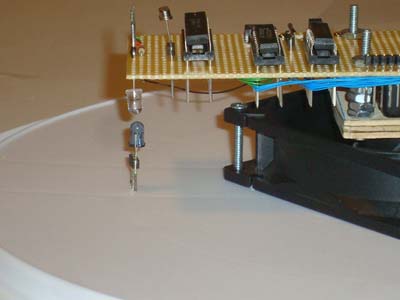
The picture seen above shows you where the 'home' location actually is on the pyro propeller clock pov. Whenever the propeller passes over the IR emitter, the phototransistor is turned on, connecting the 'collector' +5v pin to the 'emitter' ground. The PIC sees this 'falling' edge transition and knows that home was just reached.
Mechanical Hardware Design
Now that we want to start building the POV, the first thing we need to do is gather the parts, decide on a solid base to use and get the mechanical parts all drilled and screwed together.
Building The Platform
So, first off gather all of the parts together. The picture below shows you all the parts used to build the POV. The only part not shown is the +12v power supply for the fan and the IR led.
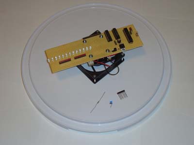
·First off we want to mount the fan to the base. 4 Nuts and Bolts will be used.
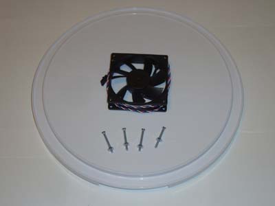
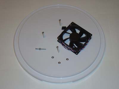
·Do your best to keep the fan centered when fastening it to the plastic base.
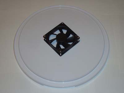
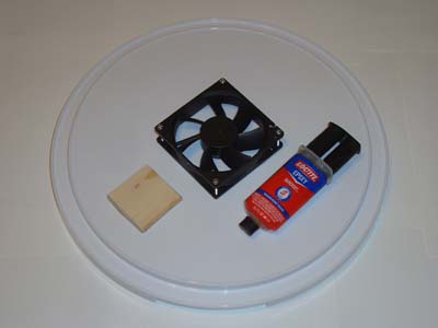
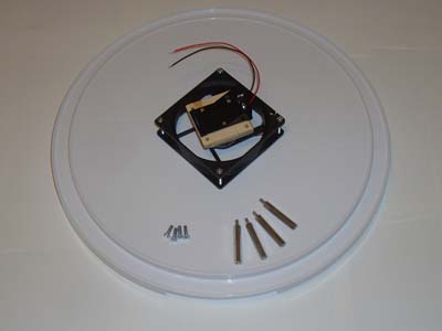
·Trim the fan blades off and mount the 9v battery holder.
·Now fasten the stand-off nuts and bolts to wood.
·Cut 4 holes into the proto-board so that you can place it ontop the stand-offs.
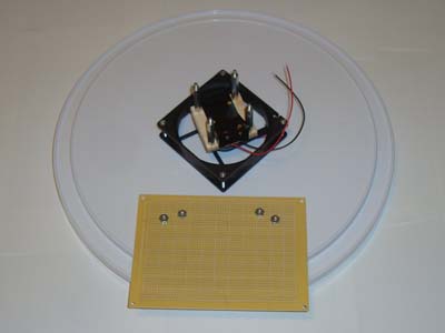
·Fasten the proto-board atop the stand-offs with some nuts.
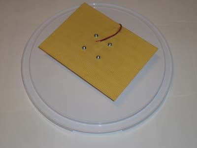
·Trim the proto-board to a smaller, more rectangular shape.
·The mechanical work is done. Now we just need to do some electrical work! (y)
Electrical Hardware Design
Strictly speaking, you just need to follow the schematic for this portion of the build process. Part placement can make the system vibrate a lot so either [a] try to balance the weight on both sides of the proto-board (you'll see later I added two coins) or [b] place the parts as close to the middle of the protoboard as possible.
Building The Circuit
Just like before, get all of the electrical parts together and let's get started soldering and wire-wrapping. As a side note: I had only seen PCB POV designs across the web and so for my design I thought I would prove to the world that an old-school wire-wrapped POV would work just as well.

·First place all of the Wire-Wrap sockets, Power Circuity and SIPs down.
·Next place the LEDs on the opposite side and as close together as possible. The closer they are, the better that output numbers or text will look.
·Now comes the time-consuming part of wire wrapping The parts together.
·First I wire wrapped the control circuitry of the PIC and Latches.
·Then I wire wrapped the LEDs up to power and the control circuitry.
·The last step is adding the IR emitter diode to the base.
·This IR diode should be attached firmly to the base......

·....and located directly under the Phototransistor on the protoboard.
·The build process is now complete. Here is the POV:
·With the POV completed, Let's load some software onto it and test it out!
CODING PART
The Software
There are two main portions of code that we are concerned with:
-High Priority RB0 Interrupt
-Low Priority Timer0 Interrupt
I'll describe these two parts of the software in the two sections found below.
High Priority RB0 Interrupt
There are two main portions of code that we are concerned with:
-High Priority RB0 Interrupt
-Low Priority Timer0 Interrupt
I'll describe these two parts of the software in the two sections found below.
High Priority RB0 Interrupt
------------« Begin Code »------------
void InterruptHandlerHigh()
{
   if(INTCONbits.INT0IF) //check if INT0 interrupt flag is set
   {
     led_count = 325;
     WriteTimer0( 0xFFE0 );
     INTCONbits.TMR0IF = 0; //Clear TMR0 Flag
     INTCONbits.INT0IF = 0;
   }
INTCONbits.GIEH = 1;
}
------------« End Code »------------
The job of this high priority interrupt is to reset the timer0 so that it starts outputting to the LEDs from the very beginning. This is how the POV effect is created, by displaying the same pattern over and over many times per second. The led_count variable seen above is used as a timer interrupt counter to know which set of LED information to output. In the INT0 interrupt service routine it also gets reset.
Low Priority Timer0 Interrupt
------------« Begin Code »------------
void InterruptHandlerLow()
{
   if(INTCONbits.TMR0IF) //check if TMR0 interrupt flag is set
   {
     WriteTimer0( 0xFE49 ); //Reset Timer0 for 43.8uS Delay
     //Set The Clock Numbers On Top
     if(led_count < 0x11D && led_count > 0x117){
     ...
     ..
     ...
     ..
     ..
     }
     else{
     set_leds(0xFFFF);
     }
     INTCONbits.TMR0IF = 0; //Clear TMR0 Flag
   }
INTCONbits.GIEL = 1; //Re-enable all interrupts
}
------------« End Code »------------
The timer0 interrupt service routine decrements the led_count value and then uses it to dynamically know which leds to turn on and off. A big set of if/else statements were used for different locations and clock numbers/text that show up on the display.
Data & Observations
After shedding all that sweat and blood, now we can finally test this pyro propeller clock out. The video below gives a quick summary of how it was built and then shows some action shots of things moving wildly 'in' control.
After shedding all that sweat and blood, now we can finally test this pyro propeller clock out. The video below gives a quick summary of how it was built and then shows some action shots of things moving wildly 'in' control.
The specific 1° intervals are easily reached by the blazing fast 40 MHz microcontroller. So much so that we are even able to do some trippy-cool stuff like display text, or create radiating images. The sky is the limit (although really the flash programming space is) of what you can display on the clock.
An Overview Of The Pyro Propeller Clock POV
This project pushed a few limits beyond a basic hobbyist project with complex software design (with priority interrupts) and demanding high speed timing requirements. The precise timing achieved by the microcontroller yields precise control over the led outputs at every angle. While this project only demanded 1° of accuracy, the 40 MHz clock speed could offer much more if we wanted it. The result of all this thinking and calculating is a the cool display of seemingly floating LEDs that can display the time, text or pretty much anything we want it to.
This project pushed a few limits beyond a basic hobbyist project with complex software design (with priority interrupts) and demanding high speed timing requirements. The precise timing achieved by the microcontroller yields precise control over the led outputs at every angle. While this project only demanded 1° of accuracy, the 40 MHz clock speed could offer much more if we wanted it. The result of all this thinking and calculating is a the cool display of seemingly floating LEDs that can display the time, text or pretty much anything we want it to.
What To Do Now
If you read through this project write-up, then I'm sure that you have seen other propeller clock POV's in the wild that are much more complicated. Those should give you ideas for other routes to explore for what else you can do to improve the project; most notably is using RGB leds so that the output can be any color that you want. Other designs have used wireless power transfer to keep the design down to 1 core power supply. These other paths are all good places to explore to build an even better propeller clock POV.
Conclusion
As it is, this pyro propeller clock POV turned out exactly as I had hoped. It is just simple enough, that I feel people can duplicate it with much less perspiration than it took me to build it, yet it still achieves the desired POV effect that looks so cool. However, the simplistic design has its trade-offs; especially in terms of reliability. The system created here could only run for a few hours before the 9v battery died, making this more of a novelty project. But if you are trying to build your own propeller clock POV for fun, then novelty is what it is all about!
If you have any further questions, I implore you...don't be shy, ask a question there. I check them out regularly and love getting comments & questions.
sir,can u give me the full coding?? i already try the coding that u give but it does work.plss. im really need your help.
Its really very cool
sir can i get a full code...i done it but i need a code to make sure it work...
sir can i get a full code...i done it but i need a code to make sure it work...
Hi Sir,
which version of mplab c18 compiler used here
hello can i get the steps how to make a propeller clock using arduino uno and also the materials needed. can i also get the code :( please we need your help , just for our project. thankyou in advance. Godbless
hello can i get the steps how to make a propeller clock using arduino uno and also the materials needed. can i also get the code :( please we need your help , just for our project. thankyou in advance. Godbless